HDMI Switch Reversing
PortTa HDMI Switch 4:1 with Audio
Nearest archived product page I could find
Phil bought one of the above recently to avoid excessive grubbing about behind the TV changing over between XBox, Laptop(s), PS4, DVD player… you get the idea. It was cheap, it kind of worked. Unfortunately it had a couple of features that made it useless in my circumstances: no auto-switching to active input; overlapping IR codes with my Humax box (change channel on the Humax and the switch powers down!)
Needless to say I have had no joy asking the vendor for info on fixing these bugs, so I could send it back and try another brand, or.. open it up :) Turns out a couple of folks have taken a look inside similar devices, mostly to hack round HDCP protection, so I have some idea what to expect and indeed it’s pretty unexciting:
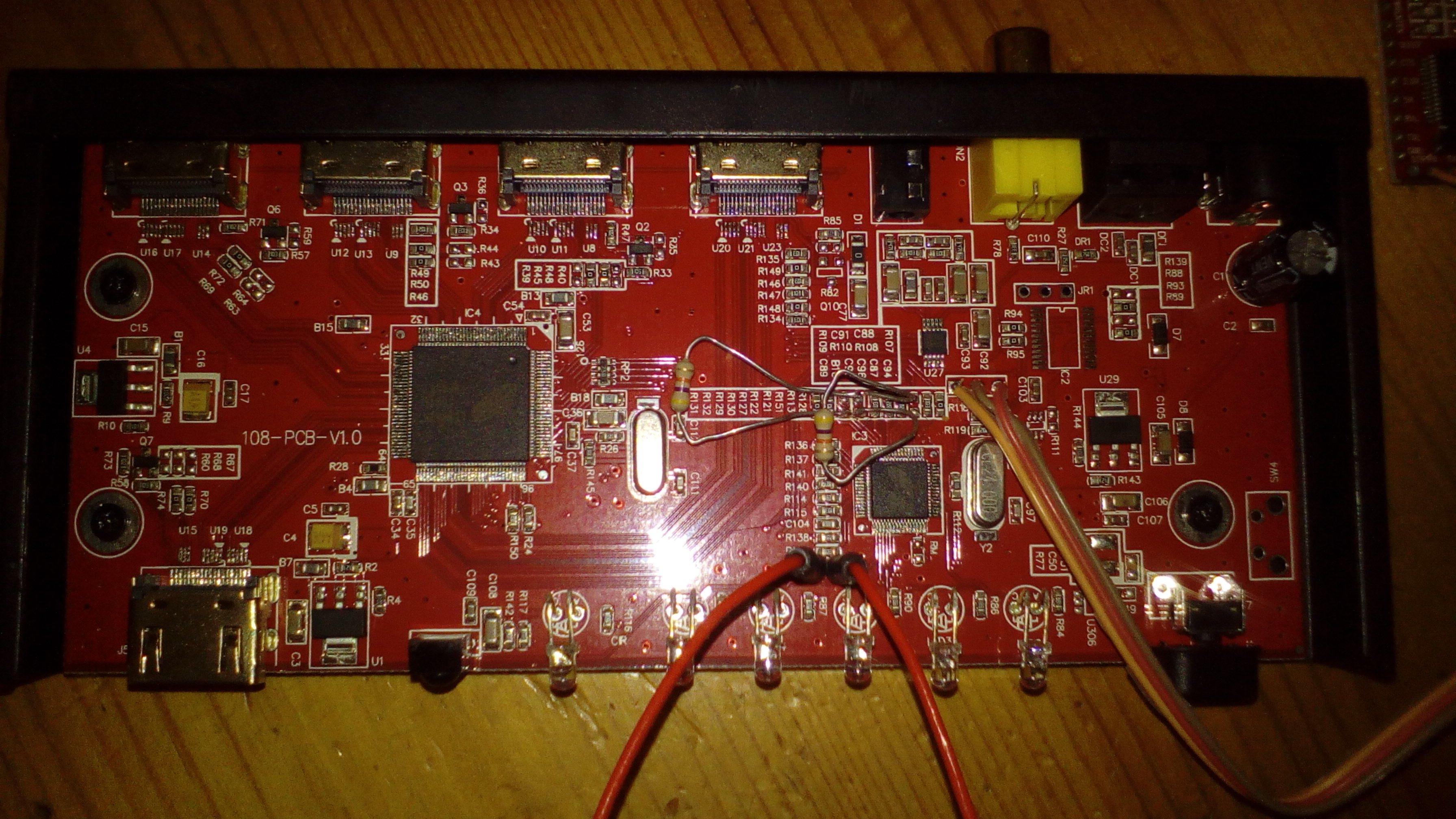
There’s a couple of devices from Explore Microelectronics that do the work (EP94A1K: HDMI switch, EPF021A: MCU), an SPI audio DAC to provide analogue outputs and some lights and buttons.
I grabbed the data sheets for the MCU device (or similar, as they’re closed source / NDA stuff) and after much Internet hunting also found some programming tools written in C#/.NET for XP that may work with the MCU (EPF021A).
The plan:
* activate the ICP (in-circuit programming) mode in the MCU
* extract the existing firmware, prove I can re-program the device
* put a toolchain together that can build new firmware
* write some open-source firmware to fix my bugs and anyone else's
The ICP protocol is badly documented (aka missing), so that needs reversing from the C#/.NET tools; the PCB is missing the necessary pull-up resistors for the serial port (normal anti-reversing / cost saving trick); I don’t know if the ICP allows reading the firmware out (see below!).
Hardware first
The EPF011/021 data sheet indicates serial port pins, which appear to be brought out to solder pads (nice), however the pull-up resistors have been left off and I need to borrow a TTL-serial adapter (thanks Jason!) A bit of soldering later and all is good here. Baud rate - get the ‘scope out and measure the pulse width, looks like ~17usecs/57600 which matches the screenshots in the dodgy manual for the programming software.
Serial traffic
So, does it say anything when powered up? fire up minicom and configure as 57600/8N1. Yes! Hello KL113 software :) I see some debug info at boot, and more when pressing the channel change button. Out of curiosity I poked at my keyboard and was surprised to see a message “DBGCMD Buffer Full”, ah-ha, looks like I can interact in some way with the firmware.. we’ll come back to that!
What about ICP mode (the data sheet says a pin needs tying to Vdd at boot - that too is usefully brought to a pair of pads)? Unfortunately the data sheet says nothing about the device being erased if you enable ICP mode, time to take a risk. Pop a jumper across the pads, and power up: I get a continuous stream of semi-colons on the serial port, probably some kind of synchronisation / detection, and no smoke. Power down, take off the jumper and re-start - it’s back doing normal things - phew!
Take apart the programming tool
So what of the programming software? Well it works on XP or Win7, but sadly doesn’t have the ‘read device’ button enabled. Time to pull it apart too. My tool of choice here is dotNetPeek from JetBrains, a completely awesome decompiler that turns out almost re-compilable C# and a Visual Studio project to work in from the .exe - sweet :)
Now I have a choice, try and fix their code to enable the device read function, or re-implement from understanding the ICP protocol. Given I want to end up with Open Source (not decompiled!) code, I’ll re-implement. Following the rather badly structured application down to the serial port I/O I get the following to read the device:
Bootstrap:
- wait for a sequence of ';' characters (at least 10)
- write '5', wait to see if ';' chars stop. Repeat if not (up to 4096 times)

Read Flash (one 512 byte block):
- set mode (read) and address (multiple of 256)
  - write 139 (dec) followed by (addr >> 8)
  - read byte, confirm 139 (dec)
  - write 85 (dec)
  - read byte, confirm (addr >> 8)
  - write 85 (dec)
- start command execution
  - write 140 (dec)
- read block bytes and ack
  - read 512 bytes
  - write 85 (dec)
- read block end and ack
  - read byte, confirm 136 (dec)
  - write 85 (dec)
..and for the brave to write to it:
Bootstrap (as above)

Write flash (one 512 byte block):
- set mode (write) and address (multiple of 256)
  - write 138 (dec) followed by (addr >> 8)
  - read byte, confirm 138 (dec)
  - write 85 (dec)
  - read byte, confirm (addr >> 8)
  - write 85 (dec)
- start command execution
  - write 140 (dec)
- write block of bytes
  - write 512 bytes
- read block end and ack
  - read byte, confirm 136 (dec)
  - write 85 (dec)
NB: in both cases, the address must be a multiple of 512 (flash block size), or the device will return an error code in place of the command echo.
This seems easy enough to replicate in clean code, and indeed it worked first time, I have a flash dump.
Getting a new toolchain working
I picked the readily available (standard package) sdcc compiler and
fiddled with it’s settings to reduce the junk it emits for 8051 targets,
writing my own boot.asm minimal startup and a couple of very short
test programs (blinkenlight obviously, and a serial port reflector).
The Makefile does a little more fettling with sdobjcopy to convert
the Intel hex output of the linker to a binary image, and it works :)
That’s it for now
Code here in Sourcehut.